Published On Sep 1, 2019
In this video, the Bipolar Junction Transistor, its different regions of operation, different configurations, and the working is briefly explained.
By watching this video, you will learn the following topics:
0:00 Introduction
0:20 What is BJT?
1:12 Construction of BJT
3:24 Different Regions of Operation of BJT (Active, Saturation, and Cut-off)
6:20 Symbols of NPN and PNP transistor
7:05 Different Configurations (CE, CB, and CC)
8:03 Working of BJT
12:30 Different Currents in BJT
What is Bipolar Junction Transistor (BJT)?
Bipolar Junction Transistor is a 3 terminal semiconductor device that can be used as a switch or as an amplifier in electronic circuits.
The reason it is known as bipolar is because there is a flow of current in BJT due to two types of charges (unlike FET)
Holes and Electrons
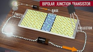
Construction of BJT:
The BJT consist of the three doped regions. The three regions of the BJT are known as Emitter, Base, and Collector.
And based on the doping of the three regions, it is known as either NPN or PNP transistor.
In BJT, the emitter is heavily doped, Base is lightly doped and the collector is moderately doped.
The width of the base region is much smaller than the other two regions.
The job of the emitter region is to supply the electrons (that's why it is known as the emitter)
While the collector region collects the electrons supplied by the emitter.
Different Regions of Operation of BJT:
The BJT can be operated in the following regions:
1) Active Mode (BE Junction is Forward Biased, CB junction is reverse biased)
2) Cut-off Mode (Both BE and BC junctions are reverse biased)
3) Saturation Mode ( Both BE and BC junctions are forward-biased )
4) Reverse Active Mode (BE junction is reverse biased, BC junction is forward biased)
Different operating Configurations of BJT
When BJT is used as an amplifier, it can be configured in the following configurations:
1) Common Emitter (CE ) Configuration
2) Common Base (CB) Configuration
3) Common Collector (CC) Configuration
And at the end of the video, the working of the BJT in the active region has been explained and the relationship between the different BJT current has been established.
In this video, the basics of the BJT is explained. By watching this video, you will learn the different configurations, different types of BJT, symbols of BJT, working of BJT and different current and their relation in BJT.
This video will be helpful to everyone in understanding the basic of Bipolar Junction Transistor (BJT).
#BJT
#Transistor
#BipolarJunctionTransistor
Follow me on Facebook:
/ allaboutelecronics
Follow me on Instagram:
/ all_about.electronics
Music Credit:
http://www.bensound.com/