Published On Apr 15, 2024
How does an NE555 Timer IC work?
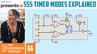
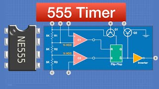
The internal circuit of the 555 timer IC consists of several sections, namely voltage divider, comparator, operational amplifier, RS flip-flop, logic gate, etc. how all these sections of 555 timer IC work and their functions are detailed in this video tutorial.
555 timer IC generally works in three modes: Astable, monostable, and bistable.
This 555 timer IC series tutorial contains detailed explanations with astable multivibrator, monostable, and bistable circuit diagrams. Also, there is a block diagram of NE555 IC.
Some more important content in this video
• What is the function of the comparator in the 555 timer IC?
• In 555 IC, what is the function of RS Flip-Flop?
• What is the function of voltage divider
• How the internal voltage divider of 555 timer IC works
• What is the function of the operational amplifier (Op Amp) of 555 timer IC
Applications of 555 Timer IC-
• Tone generation
• LED Flushers
• 555 Timer IC Oscillator Circuit
• Clock Puls for Digital Circuit
• Pulse Generations
• 555 IC Timer Circuit
• Motor Speed Control
• Pulse Width Modulation (PWM) Signal Generations
• Audio Amplifier (Low Power)
• DIY Remote Controlling Application
• Boost Converter and Buck Converter
• Automatic Water Pump
• 555 Timer IC Switching Circuit
----------
The second and third parts of the 555 timer IC tutorial will have the following topics-
How do I use 555 Timer IC as a switch?
What is the basic circuit of a NE555 timer?
What is the switching frequency of 555 IC?
How is 555 IC used as a switching circuit in the bistable mode of operation?
What is the operation of the 555 timer in astable mode?
What is the operating mode of the 555 timer?
What is the operation of the 555 timer circuit?
What is the operation of an astable multivibrator?
555 Timer IC Pin configuration.
------------------------
555 Timer IC 2nd part video link -
The video is under construction and will be uploaded as soon as possible.
------------------------
555 IC Adjustable Delay Timer Circuit Diagram-
https://www.ornatepixels.com/2024/03/...
-----------------
#555timer #ornatepixels