Published On Feb 17, 2020
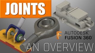
In today’s video, we’re going to continue our series on simulating joint movement in Autodesk Fusion 360 by talking about how to simulate a worm gear.
FUSION 360 JOINT TUTORIAL PLAYLIST
• Creating MOVING HINGE JOINTS in Autod...
Note that in this video, we’re going to talk about how to simulate the movement of the joint, not how to model the actual gear pieces. For the gear pieces, we’re going to use components from inside the McMaster Carr component library.
McMaster Carr Component Library Info
• FREE Hardware Component Library for A...
To start off, let’s download a worm component, as well as a worm gear. In this situation, let’s download a worm with a key of 12, and a worm with a 12 pitch and a 20:1 gear ratio.
Once we download these, we’re going to align our gears. This is actually a bit easier than aligning the bevel gears like we did last week. Notice that if you use the standard views with the view cube this is a lot easier.
Now, we need to add a couple empty components. These gears actually need to rotate around a point in space, rather than each other, so we need to have a couple components to link the as-built components to.
In these empty components, add an axis along the center of your object. We’re then going to create an as-built joint between this axis and our gears. This will allow them to rotate in place. These will be revolute joints because they spin around a point.
Now, let’s create a motion link between the two joints. In this situation, since the speed ratio is 20:1, we need our worm to spin 20 times faster than our gear, so our gear would be set to 360 degrees/20, and our worm would be set to 360 degrees.
Finally, we'll add a handle with a rigid joint between the handle and the worm gear!