Published On Jun 14, 2020
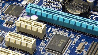
In this video from ITFreeTraining I will look at all the different connectors on the motherboard. If you are planning on building a computer or upgrading a computer, you will need to understand what all these connectors do and how to plug them in.
Download the PDF handout: http://itfreetraining.com/handouts/ap...
Motherboard Diagram
0:14 Every motherboard, I have yet to see one that has not, will have a diagram in the manual showing the locations of all the connectors on the motherboard. If you have trouble locating a connector, have a look in the manual. If you don’t have the manual, you will be able to download a copy from the motherboard manufacturer’s website.
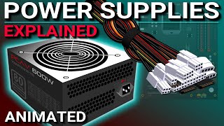
Main Power Connector (P1)
0:33 To start with, I will have a look at the main power connector, otherwise known as the P1 connector. The connector will be 20 or 24 pins in size. The 20-pin size is an old connector and unless you’re working with an old computer you won’t come across it. Most power supplies will have a 24-pin connector that can be divided into a four pin and 20 pin plug if required.
With some power supplies, the connector will be all one part and cannot be divided. If you come across this and need the 20-pin connector you have two choices. You can purchase an adapter to change the 24-pin plug to a 20 pin plug or you can attempt to plug it in anyway. It will go in, but will be a tight fit and four of the pins will be hanging out of the plug. Just make sure if you do this that you are plugging it in the right way.
You will notice this P1 connector is 24 pins, however it can be divided into two separate plugs. This motherboard has a 24-pin connector so I will combine it back into one plug.
Every connection on a motherboard nowadays is keyed. This means it is not possible to put a connector in the wrong way unless you use a lot of force which most likely will damage something in the process. If you find you are having to force a connector, double check the plug, you probably have it the wrong way around.
You will notice that the plug on the motherboard has a small notch. This will hook onto the latch on the plug. I will now plug in the P1 connector. When the P1 connector goes into place, you should hear a click.
The click is the latch on the plug; once you hear that, you know the P1 connector is in place. Once the P1 connector is plugged in, five volts of power is supplied to the computer continuously. Essentially the computer is in standby mode and this five-volts powers standby devices. For example, if you have wake-on-LAN, the five volts allows the computer to monitor for a wake-on-LAN event and start the computer up. It is possible to have devices like the keyboard start the computer from standby if your computer supports it.
As time moved on, computers required more and more power. First, the 20-pin connector was not enough and then the 24-pin connector was not enough.
P4 Connector
2:54 In 2003 the power supply standard was updated to include what is commonly referred to as the P4 connector. The P4 connector is a four-pin cable supplied by the power supply. It supplies the motherboard with additional power.
The P4 connector is generally near the CPU. Like the P1 connector, it can only be plugged in one way and you should hear a clicking noise when it is in place. Don’t get this confused with the extra four pins of the P1 connector. These connectors are not compatible and are keyed differently.
If you find that your power supply does not have the P4 connector, you can always purchase an adapter cable. In some cases, you will find that some of the older motherboards may still work without a P4 connector. You may start experiencing problems if you add new or additional video cards that use a lot of power. New motherboards tend to require the P4 connector and won’t start up without it.
The extra power supplied by the P4 connector was good, but as time passed, there was a need for even more.
EPS 12V
4:00 To provide more power to the motherboard, the four pin P4 connector was expanded to an eight-pin connector. This is called the EPS 12V. Most of the time it will be referred to just as the EPS connector.
Description to long for YouTube. Please see the following link for the rest of the description. http://itfreetraining.com/ap/1b90
References
“The Official CompTIA A+ Core Study Guide (Exam 220-1001)” Chapter 3 Position 8196-8785
“Power supply unit (computer)” https://en.wikipedia.org/wiki/Power_s...)
“Computer fan control” https://en.wikipedia.org/wiki/Compute...
“M.2” https://en.wikipedia.org/wiki/M.2
“Trusted Platform Module” https://en.wikipedia.org/wiki/Trusted...
Credits
Trainer: Austin Mason http://ITFreeTraining.com
Voice Talent: HP Lewis http://hplewis.com
Quality Assurance: Brett Batson http://www.pbb-proofreading.uk