Published On May 9, 2022
This video is sponsored by PCBWay. Prices starting at $5 per 10 PCBs!
Order yours here: https://www.pcbway.com
Content:
0:11 Hot plate enclosure
0:45 Thermistors placement
1:38 Heating elements
2:10 Glueing the heating elements with silicone
2:57 Drilling the hot plate holes
3:26 Marking the wooden base
3:55 Milling and drilling
5:28 Rounding the corners and sanding
5:48 Assembling 3D printed foot
6:12 Power module
6:33 Wiring slots
7:08 Applying water-based dye
7:45 Components assembly
8:36 Soldering the microcontroller PCB
9:00 PCBWay sponsor video
9:57 Soldering the lighting PCB
10:41 Completing the hot plate assembly
11:47 Final test
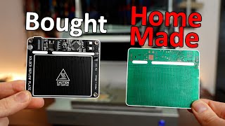
After soldering my PCBs for a while with a clothes iron, I thought it was time for an upgrade. I searched for some commercial units but I did not find any that would fit my needs. They were all either too big or too small. I wanted a medium-size hot plate with enough power to solder the type of boards that I usually work with. Since I had to be able to record the soldering process, I discarded the idea of purchasing a reflow oven like the popular T962. Being an enclosed unit was not going to help with that, and they are not cheap either. Therefore, I decided to build my own. As always, I strive for a professional, clean and minimalistic look, but this time I wanted to use wood as the base material, and attach all the other parts to it. That was a challenge for me, because I have very little experience (and tools) to do it. It would have been great to have access to a CNC router, for instance, but I found my way to do it by designing some 3D printed adapters and fixtures, and used a regular mini drill.
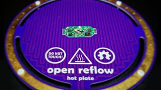
The hot plate consists of an aluminum die-cast box that heats up thanks to 3 x 230 V / 150 W heating elements. These are glued to the top of it using a thermal resistant silicone, and they are the most powerful models I could find, being able to reach up to 270 °C. Nevertheless, the generous exposed area of the hot plate radiates a lot of heat, so the top surface of the plate will never reach such a high temperature. In fact, after some tests, I decided to order some more heating elements to add some more power, and be on the safe side.
These modules are connected in parallel, and a 40 A solid-state relay is responsible for switching them on and off. The temperature is monitored using a couple of NTC100k thermistors, also placed at the top of the plate, in an equidistant position. That temperature is displayed on the embedded 0,96’’ OLED display. A simple push button, with an incorporated red LED, lets you turn on and off the machine, both in manual and automatic mode. Finally, yet importantly, 12 RGB WS2812B SMD LEDs give the final touch to the build, and help me visualize the temperature state of the plate by changing its color.
I considered using an ESP32 microcontroller, as I have been doing on my latest projects, but I did not need WiFi nor Bluetooth connectivity, so I thought that using a simpler Arduino board instead was more than enough in this case. In addition, this way the PCB design was easier and faster to complete.
I used my trusty 3D printer to make four legs, and a bottom cover to hide all the wiring. I chose a silver silk filament for that, and I printed it on glass to give it a smooth and shiny look.
I hope you enjoy the video! Stay tuned for the next one.
Links:
Instagram: / elite_worm
GitHub: https://github.com/eliteworm